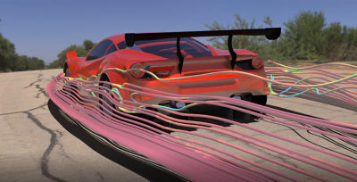
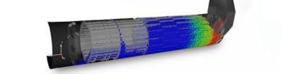
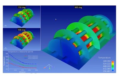
Aero Concept Engineering uses CFD visualization PDF Print E-mail
by Bob Cramblitt

Designing a LeMans Prototype 2 (LMP2) car could be considered the ultimate challenge for an aerodynamicist.

Obviously, the car has to be fast, but it also has to be durable and reliable to maintain competitiveness over 24 hours of racing.  It has to meet stringent safety specifications of LeMans’ governing body, ACO (Automobile Club d l’Ouest), and be stable enough that it doesn’t soar off the track, as three Mercedes Benz CLRs did in 1999.

There’s financial pressure as well, as a completed chassis alone can cost $600,000 or more.

The myriad challenges associated with developing endurance race car prototypes has some speculating that there will be fewer new designs in the LMP2 category, which specifies a car that at 775 kg (1,709 lbs.) is 19-percent lighter than an LMP1 category car, with engine displacement limited to 3400 cc for aspirated and 2000 cc for turbocharged engines.  Number of cylinders is capped at eight.

Entering the race

image-cfd-backOne company not intimidated by the challenges of a new LMP2 entry is Zulltec, based in the town of Nanteuil les Meaux, about 30 miles east of Paris.  Zulltec is working with another French company, Aero Concept Engineering (ACE), to maximize aerodynamics for a new prototype called the CZ-01.

ACE (www.aero-ce.com), created in 2002 by two ex-Prost Grand Prix Formula One engineers, provides complete aerodynamic consultancy and development services encompassing CFD, wind-tunnel testing, CAD, model manufacturing, and track analysis.  To meet the ever-greater challenges of developing competitive racecars, ACE combines computational fluid dynamics (CFD) results from Fluent with extreme visualization from CEI’s EnSight.

“CFD visualization is less expensive and more efficient than physical prototyping for developing wings and other design features,” says Alexis Lapouille, who manages ACE along with Xavier Gergaud.  “It enables us to solve problems that cannot be analyzed with the wind tunnel, such as those encountered when designing climate control systems, mechanical linkage (pantograph), engines, and brake intakes.”

More options in less time

image-cfd-bigfrontCFD is being embraced in all types of racing because of its ability to provide more information and a greater understanding of the relation of design changes to aerodynamic efficiency.  It also enables engineers to explore many more design options in less time and at considerably less cost than physical testing.  CFD becomes especially valuable when teamed with visualization software such as EnSight, which enables engineers to see and quantify performance characteristics that are not readily discernable in the solver’s post-processor or through physical testing.

ACE’s process starts with importing a CATIA model of the Zulltec CZ-01 car into ANSA for surface meshing, and Tgrid and Gambit for volume meshing.  The meshed model is imported into Fluent for CFD analysis.  Fluent data for each type of calculation is then loaded into EnSight, which generates isosurface, pathlines and X,Y, Z planes for visualization.  Images are generated for each calculation and compared using EnSight’s case mapping option.  Animations in 3D enable ACE to explore transient data – how airflow changes over time according to changing conditions.

“EnSight allows us to be very precise for the phenomena we want to visualize,” says Lapouille.  “If you have phenomena at X=1m on a calculation, for example, Fluent requires you to know where the phenomena is to generate the plane for visualization.  With EnSight, you generate an X plane and then simply move it until you find the phenomena.  Similarly, the vortex core feature allows you to find the vortex structure in very little time.”

Paths of least resistance

ACE takes full advantage of pathlines within EnSight, which show the movement of air or particles around and inside a vehicle.  EnSight has the unique ability to compute pathlines and add them to a parts list as geometric entities.  That enables ACE to export the pathlines to CATIA as a dataset to use for reverse engineering.  Based on the pathlines, the geometry of a specific part can be modified to develop a design that provides the least-resistant path for airflow around the part.

“This type of reverse engineering shows the value of extreme visualization,” says Lapouille.  “It gives us a greater understanding of how design changes affect flow field, vortices and energy loss around the car.”

image-cfd-diagBased on the initial design and changes derived from CFD optimizations, ACE manufactured a 33-percent scale model of the Zulltec CZ-01 for wind-tunnel testing.  

The ACE wind tunnel is a rolling-road model that was purchased from Prost GP after the team folded in 2002.  Originally built in 1991 for the Ligier Formula One team, it provides wind and belt speeds up to 40 m/s, and can accommodate physical models ranging from 25 percent to full scale, depending upon the vehicle.  ACE uses the wind tunnel extensively for both original development of car designs and CFD verification.

Verifying results in the physical world

ACE tests all design configurations generating good CFD results in the wind tunnel to verify the computer-simulated results in the physical world.  Design configurations that yield poor results are sometimes tested as well in an attempt to uncover what factors are adversely affecting airflow.

The wind tunnel is used to compare surface flow results to pathline visualizations with surface restrictions applied in EnSight, and to compare drag and lift for different designs and conditions.  In all tests, ACE finds a close correlation between CFD and wind-tunnel results.

image-cfd-rearwingAlthough for competitive reasons ACE cannot divulge exact changes made as a result of CFD visualization, Lapouille says the process has led to changes in the design of the CZ-01 engine intake, front and rear wings, and specific areas of the car such as the engine cover.


“There were a lot of surprises that we uncovered through the CFD visualization process – things we couldn’t have uncovered otherwise,” says Lapouille.  “Unfortunately, I cannot talk about those surprises without helping our competitors.”The effects of those changes and the level of the surprise factor will be seen in test runs scheduled later on this year, after which further modifications will be made before the car is prepared for competition, most likely in 2007.


More Information

CFD visualization is becoming a major tool for racing teams seeking to gain a competitive advantage by designing more aerodynamically efficient parts and assemblies in much less time.

Here are additional resources and case studies:

Aero Concept Engineering (ACE): www.aero-ce.com
Advantage CFD: www.advantage-cfd.co.uk

•    CFD visualization helps DaimlerChrysler accelerate return to NASCAR fast track, daimlerchrysler.pdf
•    UMR racing team uses advanced visualization to overturn conventional aerodynamic wisdom, fsae.pdf
•    Prodrive speeds Ferrari wing development with reverse engineering & CFD technologies, www.geomagic.com/en/solutions/prodrive.php


Link to October 17, 2006 Designfax issue


valid xhtml? | valid CSS?

Joomla Templates by Joomlashack